Laser Profiling Case Study
Laser Profiling Case Study 2024

Laser Profiling Case Study
Written by Joseph Marland-Brown of CTS Ltd
In February 2024 testing and analysis has been conducted on a laser profiling system to ascertain its pros and cons for measuring the inside surface of pipes.
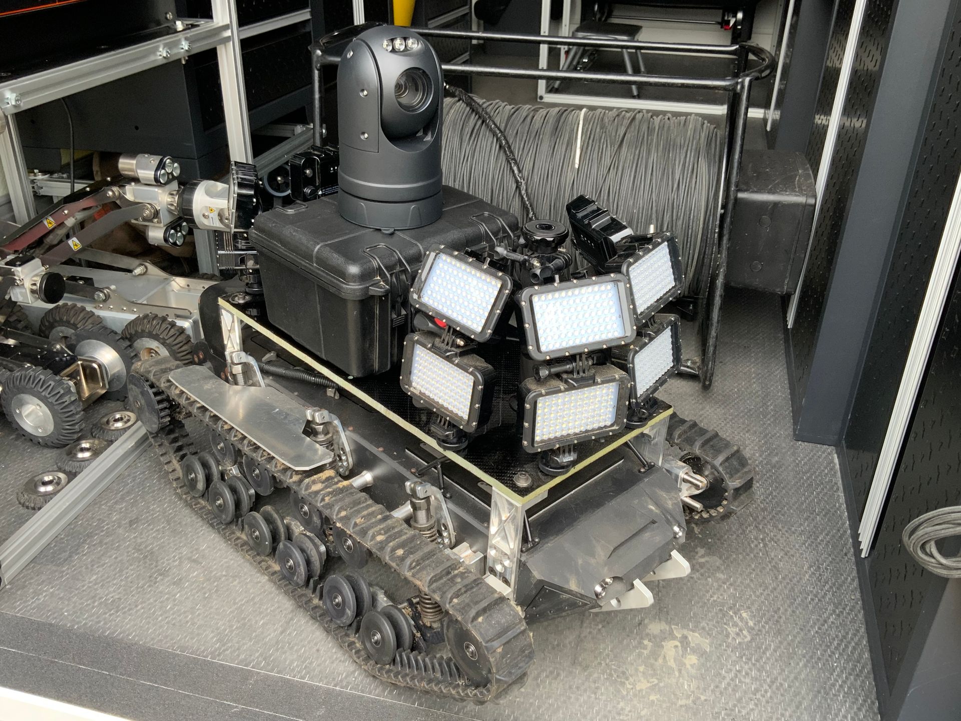
The hardware was a single class 2 red laser with a conical lens fitted, powered by battery and approximately 20mm diameter by 75mm long, the laser module is fitted to a rod which in turn is mounted to a camera housing on the front of a CCTV crawler system, the rod is made of small sections which screw together to extend the laser module at different distances away from the camera. The laser and rods could be retro fitted to any Crawler system.
The laser module is made of metal and glass and could be damaged if dropped or scraped along with the inside of a pipe, the laser modules are expensive and not readily available in the industry from suppliers, in the UK there is one supplier and the rest being in Europe,
The technology of lasers dates to 1900s Max Planck Kicks it All off, followed by Einstein’s Concept and Theory of Stimulated Light Emission, the Rise of MASER (Microwave Amplification of Stimulated Emission of Radiation) in 1954, then led to Gordon Gould in 1957 Coining the phrase of Laser, this led to mainstream innovations using this technology to now,
How does a laser distance meter work?
In a nutshell, laser measurement tools are based on the principle of reflection of a laser beam. To measure a distance, the device emits a pulse of laser in the direction of an object, for example a wall. The time necessary for the laser beam to get to the object and go back determines the measurement of the distance. In consideration of the speed of light, distances can be defined precisely with this kind of laser. Laser distance meters can also accumulate independently to calculate surfaces and volumes.
A Laser Profiling system for pipes was made approx. 15 years ago in New Zealand, Software has also been designed to read the laser data to form a report for others to gain an understanding of the inside measurements and ovality of pipes.
At this stage we must understand how this system works, the first very important note worthy feature of the laser profiling system is that it does not measure, it emits a red ring on the inside of the pipe by shooting the laser light at the conical lens which in return reflects the light 360 degrees to create a single red line on the nearest surface to the lens, the light ring is thin and measures 2mm from its outside edges. it will take the form of any shape.
Setting up the system is reasonably straight forward to trained professionals but can be confusing to others, once the equipment is put together the crawler has to be placed into the pipe, this is the most likely time damage will occur, with the rod sticking out up to 400mm and with the length and weight of crawler deployment with out man entry is difficult, the standard size of a manhole for a 400mm pipe is a 580mm internal square shaft, so the system must be lowered vertically and then swivelled upwards to set the crawler horizonal whilst attempting to guide the rod into the pipe, man entry and assembling in the manhole would prevent accidental damage to the laser module.
Once set and in place the crawler must be driven along the pipe whilst recording CCTV for general condition, the video will see the rod and laser module which blocks part of the view, a condition survey can still be gained. Once the crawler reaches the end of the survey length, the operator must switch of all the lights on the crawler, it is recommended that if the pipe has an open end a cover is put over the pipe to reduce the natural light, the crawler must then be reversed out of the pipe until it reaches its staring position, again a cover would help at the staring point to reduce the natural light, whilst this operation is going on the CCTV camera is recording video, basically its seeing a black background and a red light ring. Its is also recommend that any clever settings to enhance the imagery are all switched off.
As you can imagine reversing a crawler in the dark over long distances i.e. 50 meters and more is an uncontrolled process, the crawlers are generally steerable but without any light steering becomes in affective and if chanced could tip the crawler over, there are some guides on the software screen which indicate the level of the crawler but are not that accurate and really only used as a rough guide, a cradle can be fitted to the crawler to prevent tipping, that said in a 445mm pipe it’s not too difficult to reverse even in the dark, its when larger pipe diameters are attempted that the process becomes more cumbersome.
It is also worth noting that any water in the pipe will affect the laser light as laser will only reflect off the water and not give a fully formed ring, the video image also captures the rod so there is a break in the laser ring when viewing the video film.
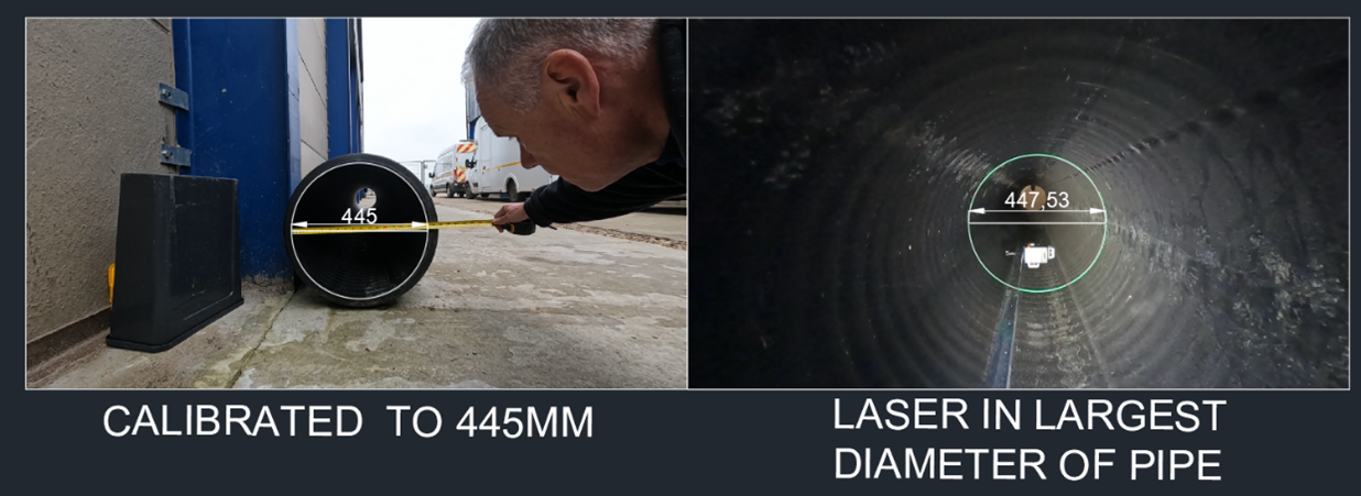
To create a perfectly formed ring laser in a pipe the crawler must be aligned to the pipe both horizontally and vertically with the laser module central, as the crawler moves position the light ring moves with the orientation of the crawler, this will later lead to inaccurate analysis of the light ring survey. The accuracy is said to be 3% of the diameter of the pipe, so in a 445mm pipe this would be in perfect conditions, 3% of 445mm is 3 x 445mm over a 100 = 13.35mm.
After the survey is completed the software can then analysis the video and light ring created in the video, this is where the measurements take place, the first process is to Calibrate the laser using the video and a ruler, then the measurements can be put into the software, the software can then work out from the calibrated measurement the diameter of the light ring emitted onto the pipe interior surface and also gives a picture of the video from the survey, the video will be imported into a X,Y,Z environment commonly used in measuring software, from the still images measurements can be taken, the software will also analyse the red ring and draw around it, putting multiple rings together can then create a 3d cad model,
because the laser profiler hardware and crawler system do not have built in IMUs the 3d model cannot be relied on for longitudinal differences in the pipe or any bends however slight.
Summary,
Laser profiling is a good way of obtaining measurements of the inside of pipes, the users must take as much care in calibrating to give the best results, the uncontrolled process is a concern, whether the data and report are sufficient for design purposes is solely at the designer’s risk and could have expensive repercussions in a manufacturing process for pipe rehabilitation.
Next steps…
After this testing and analysis other ways have been considered to provide internal measurements of pipes, Laser scanning and Laser profiling are the best methods, with: Laser Scanning taking precedence over profiling as Laser scanning measures in real time by time of flight and return of the laser from a solid surface,
Laser profiling can be improved on, Ive taken into account the hardware, software set up and usage of the current system, The first thing to overcome is carrying out a survey in a more controlled manner, this can be achieved by using Green class 1 lasers, also the video resolution of CCTV camera on Crawler system is analogue with a video resolution of 720 x 480 with a small field of view. This can be increased to 1920 x 1080. Field of View Horizontal (In Degrees) of 92 and a Field of View Vertical (In Degrees) of 61. This allows for larger pipe diameters to be achieved. The resolution is also greatly increased giving a much higher pixel count which leads to more accurate measuring. Example Below (Note: Fisheye lenses will distort the image)
· 720 x 480 = 345,600 pixels no HD,
· 1920 x 1080 = 2,073,600 pixels HD
Having a controlled environment with a much higher resolution camera gives the Designer clearer detailed imagery, additional low light can be added to enhance the condition survey and not affect the laser in any way, the movement of the crawler can be controlled as you can see where you are in the pipe, greater diameters can now be achieved, a single pass can be carried out while the laser ring is visible in the lighted conditions, and overall the process becomes more efficient with controlled results.
From the video software’s can be used to extract out imagery, these images can then be imported into a CAD program, after scaling and aligning data can be extracted from the image,
The benefits are you can see the picture of the inside of the pipe with the light ring, inspect if theirs encrustation, water or any other foreign objects, that will lead to inaccurate measurements, create circles to overlay on the images and draw around the light ring when its deformed, this process is not automatic, the cad operator has to pay particular attention to the process and thus learning more in detail about the condition and size of the pipe.
The rings created can be made into a solid 3d model, and other solids can be fitted inside to see if they fit, we must be careful of heave, sagging, crushing and bends in the pipe, (Note: Laser Scanning the pipe will remove all these essential criteria’s)
We are now evaluating a new system which we have built and will report on the accuracies when final testing is completed, the initial testing gave a 0.5mm reading between two light rings in a 445mm ribbed land drainpipe tested at our Workshop in a controlled and measured environment. Further testing returned results of tolerance 0.61mm, tolerance 1.86mm & tolerance 2.18mm, we believe a safe number to work from would be 3mm accuracy which in turn reduces the 3mm percentage rate down to 0.5%.
Joseph Marland-Brown
(Contracts Manager) 07920429070, Joseph@ctsltd.info, www.ctsltd.info
CTS are now ready to supply this service.


